| Homepage |
| Code Division |
| Diversity Technique |
| Channel Coding |
| Multi User Detection |
| Reference |
Spread Spectrum
| Generality for spread spectrum |
| Direct Sequence spreading, spread spectrum signal(DS-SS) |
|
Spreading Codes for ISI Rejection: Pseudorandom and m-Sequences |
Whereas conventional modulation techniques strive to achieve greater power and bandwidth efficiency and minimize the required transmission bandwidth, spread spectrum technique employ a transmission bandwidth that is several orders of magnitude greater than the minimum required signal bandwidth, while this system is very bandwidth inefficiency for a signal user, the advantage of spread spectrum is that many users can share the same bandwidth without significantly interfering with one another. In a multiple-user, multiple access interference environment, spectrum system become very bandwidth efficiency.
Apart from occupying a very large bandwidth, spread spectrum signals are pseudorandom and have nose-like properties. The spreading waveform is controlled by a PN sequence or PN code. Spread spectrum signals are demodulated at the receiver through cross-correlation with a locally-generated version of the PN carrier. Cross-correlation with the correct PN sequence despreads the spread spectrum signal and restores the modulated message in the same narrow band as the original data, whereas cross-correlating the signal from an undesired user results in a very small amount of wideband noise at the receiver.
Since each user is assigned a unique PN code which is approximately orthogonal to the codes of other users, the receiver can separate each user based on their codes.
Direct Sequence spreading, spread spectrum signal(DS-SS)
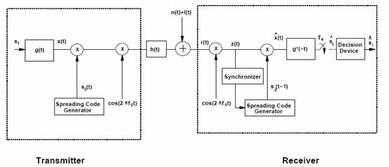
An end-to-end direct sequence spread spectrum system is
illustrated in Figure 1-1. The multiplication by
![]() and
the carrier
and
the carrier ![]() could
be done in opposite order as well: downconverting prior to despreading allows
the code synchronization and despreading to be done digitally, but complicates
carrier phase tracking since it must be done relative to the wideband spread
signal. For simplicity we only illustrate the receiver for in-phase signaling, a
similar structure is used for the quadrature signal component. The data symbols
could
be done in opposite order as well: downconverting prior to despreading allows
the code synchronization and despreading to be done digitally, but complicates
carrier phase tracking since it must be done relative to the wideband spread
signal. For simplicity we only illustrate the receiver for in-phase signaling, a
similar structure is used for the quadrature signal component. The data symbols
![]() are
first linearly modulated to form the baseband modulated signal
are
first linearly modulated to form the baseband modulated signal![]() ,
where
,
where ![]() is
the modulator shaping pulse,
is
the modulator shaping pulse, ![]() is
the symbol time, and
is
the symbol time, and
![]() is
the symbol transmitted over the lth symbol time. Linear modulation is
used since DSSS is a form of phase modulation and therefore works best in
conjunction with a linearly modulated data signal. The modulated signal is then
multiplied by the spreading code
is
the symbol transmitted over the lth symbol time. Linear modulation is
used since DSSS is a form of phase modulation and therefore works best in
conjunction with a linearly modulated data signal. The modulated signal is then
multiplied by the spreading code
![]() with
chip time
with
chip time
![]() ,
and then upconverted through multiplication by the carrier
,
and then upconverted through multiplication by the carrier
![]() .
The spread signal passes through the channel
.
The spread signal passes through the channel
![]() which
also introduces additive noise
which
also introduces additive noise
![]() and
narrowband interference
and
narrowband interference
![]() .
.
DSSS Systen Model
Assume the channel introduces
several multipath components
![]()
The input to the matched filter is given by
![]() Without
multipath and interference, i.e. for
Without
multipath and interference, i.e. for
![]() and
and
![]()
![]() since
since
![]() .
If
.
If ![]() is
sufficiently wideband then
is
sufficiently wideband then
![]() has
approximately the same statistics as
has
approximately the same statistics as
![]() .The
matched filter output over a symbol time will thus be
.The
matched filter output over a symbol time will thus be

The interference signal
I(t)
at the carrier frequency
fc,
which can be modeled as
![]() for
some narrowband baseband signal
for
some narrowband baseband signal
![]() .
.
Multiplication by the spreading signal perfectly synchronized to the incoming signal is
![]()
The demodulator output is then given by

The spread interference
![]() is
a wideband signal with bandwidth of roughly
is
a wideband signal with bandwidth of roughly
![]() ,
and the integration acts as a lowpass filter with bandwidth of roughly
,
and the integration acts as a lowpass filter with bandwidth of roughly
![]() ,
thereby removing most of the interference power.
,
thereby removing most of the interference power.
Now consider ISI rejection. Assume
a multipath channel with one delayed component:
![]() .
For simplicity, assume
.
For simplicity, assume
![]() is
an integer multiple of the symbol time. Suppose that the first multipath
component is stronger than the second:
is
an integer multiple of the symbol time. Suppose that the first multipath
component is stronger than the second:
![]() ,
and that the receiver synchronizes to the first component (
,
and that the receiver synchronizes to the first component (![]() in
Figure 1-1). Then, in the absence of narrowband interference (
in
Figure 1-1). Then, in the absence of narrowband interference (![]() ),
after despreading we have
),
after despreading we have
![]()
Since
![]() the
ISI just corresponds to the signal transmission of the
(l
−
k)th
symbol, i.e.
the
ISI just corresponds to the signal transmission of the
(l
−
k)th
symbol, i.e.
![]() .
The demodulator output over the
lth
symbol time is then given by
.
The demodulator output over the
lth
symbol time is then given by

where, as in the case of
interference rejection,
![]() and
and
![]() correspond
to the data symbol and noise output of a standard demodulator without spreading
or despreading and the approximation assumes
correspond
to the data symbol and noise output of a standard demodulator without spreading
or despreading and the approximation assumes
![]() The
middle term
The
middle term
![]() comes
from the following
comes
from the following
integration:

where ![]() is
the autocorrelation of the spreading code at delay
is
the autocorrelation of the spreading code at delay
![]() over
a symbol time.
over
a symbol time.
Spreading Codes for ISI Rejection: Pseudorandom and m-Sequences
Apart from occupying a very large
bandwidth, spread spectrum signals are pseudorandom and have nose-like
properties. The spreading waveform is controlled by a PN sequence or PN code.
Spread spectrum signals are demodulated at the receiver through
cross-correlation with a locally-generated version of the PN carrier.
Cross-correlation with the correct PN sequence despreads the spread spectrum
signal and restores the modulated message in the same narrow band as the
original data, whereas cross-correlating the signal from an undesired user
results in a very small amount of wideband noise at the receiver. One type of PN
code generator is said to generate a maximum-length sequence, or m-sequence
waveform. These sequences
have the maximum period
![]() that
can be generated by a shift register of length n, so the sequence repeats every
that
can be generated by a shift register of length n, so the sequence repeats every
![]() seconds.
seconds.
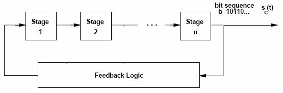
Generation of Spreading Codes
Properties of Maximum-Length Sequences:
1. In one period, the number of 1’s is always one more than the number of 0’s.
2. The modulo-2 sum of any m-sequence, when summed chip by chip with a shifted version of the same sequence, produces another shifted verson of the same sequence.
3. If a window of width r is slid along the sequence of N shifts, then all possible r-bit words will appear exactly once, except for the all 0 r-bit word.
4. If the 0’s and 1’s are represented by -1 and +1V, the autocorrelation of the sequence is

where ![]() is
the autocorrelation of the sequence and
is
the autocorrelation of the sequence and
![]()
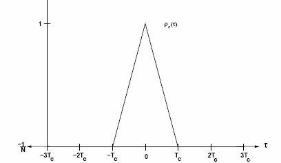
Autocorrelation of Maximal Linear Code
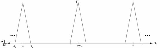
Autocorrelation has Period T=NTc
Moreover, since the spreading code is periodic with
period
![]() ,
the autocorrelation is also periodic with the same period, as shown in Figure
1-4. Thus, if
,
the autocorrelation is also periodic with the same period, as shown in Figure
1-4. Thus, if
![]() is
not within a chip time of
is
not within a chip time of
![]() for
any integer
for
any integer
![]() ,
,![]() .
By making
.
By making
![]() sufficiently
large, the impact of multipath at delays that are not within a chip
sufficiently
large, the impact of multipath at delays that are not within a chip
time of
![]() can
be mostly removed.
can
be mostly removed.