| Homepage |
| Code Division |
| Spread spectrum |
| Channel Coding |
| Multi User Detection |
| Reference |
Diversity Technique
| Generality for diversity technique |
| Derivation of selection diversity improvement |
| Derivation of maximal ratio combining improvement |
| Rake receivers |
Diversity exploits the random nature of radio propagation by finding independent (or at least highly uncorrelated) signal paths for communication. The diversity concept can be explained simply. If one radio path undergoes a deep fade, another independent path may have a strong signal. By having more than one path to select from, both the instantaneous and average SNRs at the receiver may be improved, often by as much as 20dB to 30dB.
There are two types of fading, one is small-scale fading and the other is large-scale fading. Small-scale fades are characterized by deep and rapid amplitude fluctuations which occur as the mobile moves over distances of just a few wavelength. These fades are caused by multiple reflections from the surroundings in the vicinity of the mobile. In order to prevent deep fades from occurring, microscopic diversity techniques can exploit the rapidly changing signal. For example, if two antennas are separated by a fraction of a meter, one may receive a null while the other receives a strong signal. By selecting the best signal at all times, a receiver can mitigate small-scale fading effect.
Large scale fading is caused by shadowing due to variations in both the terrain profile and the nature of the surrounding. By selecting a base station which is not shadowed when others are, the mobile can improve the average SNR, this is called macroscopic diversity, since the mobile is taking advantage of large separations(the macro system differences) between the serving base stations.
Derivation of Selection Diversity Improvement
Consider M independent Rayleigh fading channels available at a receiver, assume each channel has the same average SNR given by
![]() (1-3)
(1-3)
where we assume
![]()
If each channel has an instantaneous
![]() ,
then the PDF of
,
then the PDF of ![]() is
is
![]()
![]() (1-4)
(1-4)
where
![]() is
the mean SNR of each channel.
is
the mean SNR of each channel.
The probability that a channel has a
instantaneous SNR less than ![]() is
is
 (1-5)
(1-5)
Then the probability that all M
independent diversity channels SNR are less than
![]() is
is
![]() (1-6)
(1-6)
The probability that
![]() is
given by
is
given by
![]() (1-7)
(1-7)
the PDF of
![]() is
is
![]() (1-8)
(1-8)
Then the mean SNR
![]() may
be expressed as
may
be expressed as
 (1-9)
(1-9)
where
![]() .
Equation (1-9) is evaluated to yield the average SNR improvement offered by
selection diversity
.
Equation (1-9) is evaluated to yield the average SNR improvement offered by
selection diversity ![]()
Derivation of Maximal Ratio Combining Improvement
In maximal ration combining, the resulting signal envelope applied to the detector is
![]()
where
![]() is
the signal voltage from branch I, and
is
the signal voltage from branch I, and
![]() is
the gain of each branch.
is
the gain of each branch.
Assume that each branch has the same average noise power N, the total noise power applied to the detector is
![]()
the SNR
![]() applied
to the detector is given by
applied
to the detector is given by ![]() .
.
Using Chebyshev inequality,
![]() is
maximized when
is
maximized when ![]()

Thus the SNR out of the diversity combiner is simply the sum of the SNRs in each branch.
Time diversity repeatedly transmits information at time spacings that exceed the coherence time of the channel, so that multiple repetitions of the signal will be received with independent fading conditions, thereby providing for diversity. One modern implementation of time diversity involves the use of the RAKE receiver for spread spectrum CDMA.
Often the time-varying impulse
response channel model is too complex for simple analysis. In this case a
discrete time approximation for the wideband multipath model can be used. This
discrete-time model is especially useful in the study of spread spectrum systems
and RAKE receivers. This discrete-time model is based on a physical propagation
environment consisting of a composition of isolated point scatterers, as shown
in Figure 1-5. In this model, the multipath components are assumed to form
subpath clusters: incoming paths on a given subpath with approximate delay
![]() are
combined, and incoming paths on different subpath clusters with delays
are
combined, and incoming paths on different subpath clusters with delays![]() and
and![]() where
where
![]() can
be resolved, where
can
be resolved, where![]() denotes
the signal bandwidth.
denotes
the signal bandwidth.
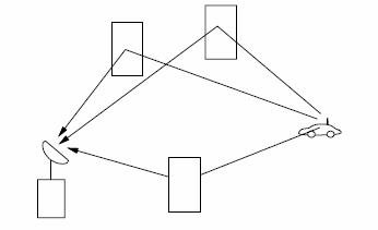
Point Scatterer Channel Model
For a fixed
t,
the time axis is divided into
![]() equal
intervals of duration
T
such that
equal
intervals of duration
T
such that
![]() where
where
![]() is
the rms delay spread of the channel, which is derived empirically. The subpaths
are restricted to lie in one of the
is
the rms delay spread of the channel, which is derived empirically. The subpaths
are restricted to lie in one of the![]() time
interval bins, as shown in Figure 3.17. The multipath spread of this discrete
model is
time
interval bins, as shown in Figure 3.17. The multipath spread of this discrete
model is![]() ,
and the resolution between paths is
,
and the resolution between paths is
![]() .
This resolution is based on the transmitted signal bandwidth:
.
This resolution is based on the transmitted signal bandwidth:
![]() .
The statistics for the
nth
bin are that
.
The statistics for the
nth
bin are that
![]() ,
1
≤
n
≤
M,
is a binary indicator of the existence of a multipath component in the
nth
bin: so
,
1
≤
n
≤
M,
is a binary indicator of the existence of a multipath component in the
nth
bin: so ![]() is
one if there is a multipath component in the
nth
bin and zero otherwise. If
is
one if there is a multipath component in the
nth
bin and zero otherwise. If ![]() then
(
then
(![]() ),
the amplitude and phase corresponding to this multipath component, follow an
empirically determined distribution. This distribution is obtained by sample
averages of
(
),
the amplitude and phase corresponding to this multipath component, follow an
empirically determined distribution. This distribution is obtained by sample
averages of
(![]() )
for each
)
for each
![]() at
different locations in the propagation environment. The empirical distribution
of (
at
different locations in the propagation environment. The empirical distribution
of (![]() )
and
(
)
and
(![]() ),
),![]() ,
is generally different, it may correspond to the same family of fading but with
different parameters (e.g. Ricean fading with different
,
is generally different, it may correspond to the same family of fading but with
different parameters (e.g. Ricean fading with different![]() factors),
or it may correspond to different fading distributions altogether (e.g. Rayleigh
fading for the
nth
bin, Nakagami fading for the
mth
bin).
factors),
or it may correspond to different fading distributions altogether (e.g. Rayleigh
fading for the
nth
bin, Nakagami fading for the
mth
bin).
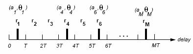
Discrete Time Approximation
This completes the statistical
model for the discrete time approximation for a single snapshot. A sequence of
profiles will model the signal over time as the channel impulse response
changes, e.g. the impulse response seen by a receiver moving at some nonzero
velocity through a city. Thus, the model must include both the first order
statistics of
(![]() )
for each profile
(equivalently, each
t),
but also the temporal and spatial correlations (assumed Markov) between them.
)
for each profile
(equivalently, each
t),
but also the temporal and spatial correlations (assumed Markov) between them.
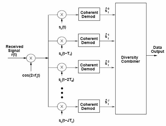
RAKE receivers
The spread spectrum receiver shown
in Figure 13.5 will synchronize to one of the multipath components in the
received signal. The multipath component to which it is synchronized is
typically the first one acquired during the coarse synchronization that is above
a given threshold. This may not be the strongest multipath component, and also
treats all other multipath components as interference. A more complicated
receiver can have several branches, with each branch synchronized to a different
multipath component. This receiver structure is called a RAKE receiver
4
and typically assumes there is a
multipath component at each integer multiple of a chip time. Thus, the time
delay of the spreading code between branches is![]() ,
as shown in Figure XXXX. The RAKE is essentially another form of diversity
combining, since the spreading code induces a path diversity on the transmitted
signal so that independent multipath components separated by more than a chip
time can be resolved. Any of the combining techniques discussed above may be
used.
,
as shown in Figure XXXX. The RAKE is essentially another form of diversity
combining, since the spreading code induces a path diversity on the transmitted
signal so that independent multipath components separated by more than a chip
time can be resolved. Any of the combining techniques discussed above may be
used.
In order to study the behavior of
RAKE receivers, assume a channel model with impulse response
![]() where
where
![]() is
the gain associated with the jth multipath component. This model can
approximate a wide range of multipath environments by matching the statistics of
the complex gains to those of the desired environment. The statistics of the
is
the gain associated with the jth multipath component. This model can
approximate a wide range of multipath environments by matching the statistics of
the complex gains to those of the desired environment. The statistics of the
![]() ’s
have been characterized empirically in for outdoor wireless channels. With this
model, each branch of the RAKE receiver in Figure XXXX synchronizes to a
different multipath component and coherently demodulates its associated signal.
A larger J
implies a higher
receiver complexity but also increased diversity. Then the output of the ith
branch demodulator is
’s
have been characterized empirically in for outdoor wireless channels. With this
model, each branch of the RAKE receiver in Figure XXXX synchronizes to a
different multipath component and coherently demodulates its associated signal.
A larger J
implies a higher
receiver complexity but also increased diversity. Then the output of the ith
branch demodulator is
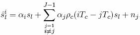
where
![]() is
the symbol transmitted over symbol time
[
is
the symbol transmitted over symbol time
[![]() ],
and we assume
],
and we assume
![]() ,
so
,
so ![]() is
also transmitted over
[
is
also transmitted over
[![]() ].
If
].
If ![]() then
the ISI term in (13.22)is more complicated and involves partial
autocorrelations. However, in all cases the ISI is reduced by roughly the
autocorrelation
then
the ISI term in (13.22)is more complicated and involves partial
autocorrelations. However, in all cases the ISI is reduced by roughly the
autocorrelation
![]() .
The diversity combiner coherently combines the demodulator outputs. If
.
The diversity combiner coherently combines the demodulator outputs. If
![]() for
for
![]() then
we can neglect the ISI terms in each branch, and the performance of the RAKE
receiver with J
branches is identical to
any other J-branch diversity technique.
then
we can neglect the ISI terms in each branch, and the performance of the RAKE
receiver with J
branches is identical to
any other J-branch diversity technique.