Brief Introduction:
The standards of GPON and EPON came out almost at the same time.However,the WDM-PON has no standard to come out, so here we only introduce the GPON and EPON and the WDM-PON will be introduced in the next sections(Key Points For PON and Solutions).
From the view of today , they are all the good implementation of FTTx(Fiber-to-the-x, i.e FTTB, FTTH, etc). Fiber-to-the-home (FTTH) is considered an ultimate
solution to meet higher bandwidth requirements in access
networks. Additionally, the next-generation access (NGA)
network based on optical fiber should be passive to reduce
the overall cost. Recently, network service providers have
begun to deploy time-division-multiplexing passive optical
networks (TDM-PONs) such as ethernet PON (E-PON), or gigabit PON (G-PON).They are all the TDM-PON,and these standards have been sufficiently matured to be employed in several countries, such as GPON in North American and EPON in Japan and Korea. Our country has constructure the EPON architecture in some cities. Also, our country pay a lot of attention to the business status of EPON and GPON.
GPON:
The gigabit-capable PON (G-PON) is specified
by International elecommunication
Union ― Telecommunication Standardization
Sector (ITU-T) G.984 series.G-PON
definition began in the Full Service Access
Network (FSAN) consortium in 2001.
The G-PON network architecture supports a
two-wavelength WDM scheme for ownstream
and upstream digital services (Fig. 1). Additionally,
another downstream wavelength is allocated
for distribution of analog video service. The network
supports up to 60 km reach, with 20 km
differential reach between optical network units
(ONUs). The split ratio supported by the standard
is up to 128. Practical deployments typically
would have lower reach and split ratio, limited
by the optical budget.
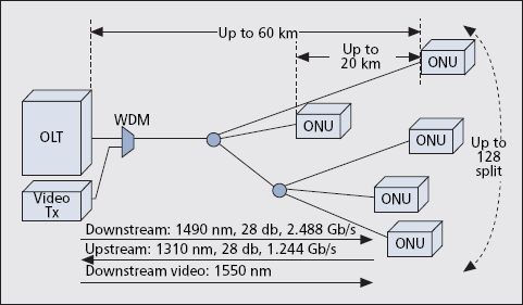
Figure3.1 GPON Physical Network Architecture
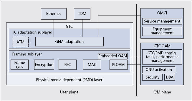
Figure3.2 GPON Functional Relationships and Layering
Active transmission equipment in GPON
network consists only of Optical Line
Termination (OLT) and Optical Network Unit
(ONU). Starting at the central office, only one singlemode
optical fiber strand runs to a passive
optical power splitter near users’ locations. At this point the splitting device
simply divides the optical power into N eparate
paths to the subscribers. The number of splitting
paths can vary from 2 to 64. From the optical
splitter, individual single-mode fiber strand run
to each user (home, businesses, etc.). The optical
fiber transmission span from the central office to
the each user can be up to 20 km.
GPON standard defines a lot of different line
transmission rates for downstream and upstream
direction.
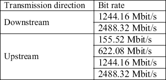
Although all combination are possible (except
downstream 1.2 Gbit/s and upstream 2.4 Gbit/s),
the most often vendors offers only 1.2 Gbit/s in
upstream and 2.4 in downstream direction.
Operating wavelength: The operating wavelength range is 1480-1500
nm for the downstream direction and 1260-1360
for upstream direction. In addition, the
wavelength range 1550-1560 nm can be used for
downstream RF video distribution.
Forward error correction: Forward Error Correction (FEC) is a
mathematical signal-processing technique that
encodes data so that errors can be detected and
corrected. With FEC, redundant information is
transmitted along with the original information.
The amount of redundant information is small so
FEC doesn’t introduce a lot of overhead. FEC
results in an increased link budget by
approximately 3-4 dB. Therefore, higher bit rate
and longer distance from the OLT to the ONU
can be supported, as well as higher number of
splits per a single PON tree.
Dynamic bandwidth allocation: Dynamic bandwidth allocation (DBA) is a
methodology that allows quick adoption of user’s
bandwidth allocation based on current traffic
requirements. DBA is controlled by OLT, which
allocates bandwidth volume to ONUs. This
technique works only in upstream direction, in
downstream direction traffic is broadcasted.To determine how much traffic to assign to an
ONU, the OLT needs to know the traffic status
of the T-CONT associated with the ONU. In
status reporting method, as part of its traffic
status a T-CONT indicates how many packets
are waiting in its buffer. Once the OLT receive
this information, it can reapportion the grants to
various ONUs accordingly. When an ONU has
no information waiting to be transported, upon
receiving a grant it sends an idle cell upstream to
indicate that its buffer is empty. This informs the
OLT that the grants for that T-CONT can be
assigned to other T-CONTs. If an ONU has a
long queue waiting in its buffer, the OLT can
assign multiple T-CONTs to that ONU.
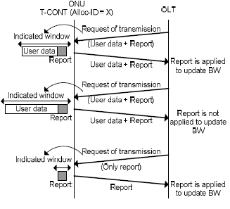
Figure3.3 DBA Process
FUTURE G-PON EXTENSIONS
A few G-PON enhancements are currently in
the works. They include the following:
? Definition of wavelength blocking filters.
The filters would be supported at G-PON
ONUs to ensure that next-generation
ONUs using additional wavelengths could
in the future be installed on currently
deployed G-PON optical data networks
(ODNs) side by side with G-PON ONUs.
? Extension of a G-PON’s optical budget to
allow deployment of longer reach and higher
split ratio. This may require an active
extender box to be deployed at the ODN.
? Inclusion of higher data rates. The downstream
rate would likely be 10 Gb/s, but the
upstream rate is still an open question of
2.5, 5, or 10 Gb/s.
EPON:
In November 2000 IEEE 802.3 announced a call
for interest for a new study group called Ethernet
in the First Mile (EFM). The group was to
extend Ethernet into the subscriber access area.
Ethernet over point-to-multipoint (P2MP)
fiber (also known as EPON) became one of the
focus areas of this group, along with Ethernet
over copper, Ethernet over point-to-point (P2P)
fiber, and OAM tracks. In September 2001 the
IEEE Standards Board approved the EFM Project
Authorization Request, resulting in the formation
of the P802.3ah task force.
EPON technology provides bidirectional 1 Gb/s
links using 1490 nm wavelength for downstream
and 1310 nm for upstream, with 1550 nm
reserved for future extensions or additional services,
such as analog video broadcast.
EPON’s rapid adoption was driven by the
early decision to define the physical layer specification
using relatively minor modifications to
inexpensive high-volume 1 Gb/s optical components.
This has greatly reduced optics cost to
levels comparable to those of continuous mode
optics.
Using the same philosophy of “define the
specification for rapid high-volume deployment,”
the EPON upstream burst lock timing was
relaxed to use available continuous mode mixed
signal components. The downside is somewhat
lower upstream utilization, but since other access
technologies are far more asymmetric, this slight
difference was deemed minor.
EPON’s Ethernet roots are unmistakable.
EPON traffic uses the same Ethernet packet
format, with standard IPG, as found in any
enterprise switch. For that matter, EPON uses
the same MAC found in any IEEE 802.3-compliant
device. The new P2MP connectivity is
supported by a protocol called Multipoint Control
Protocol (MPCP), which uses standard
Ethernet packets generated in the MAC control
sublayer.
EPON does not use encapsulating framing in
either the upstream or downstream direction;
instead, the content of the Ethernet preamble is
modified. An upstream burst is simply a
sequence of Ethernet packets with regular IPG
between them, preceded by a longer sequence of
IDLE codes used for receiver synchronization.
Any management or control information is delivered
in normal Ethernet frames.
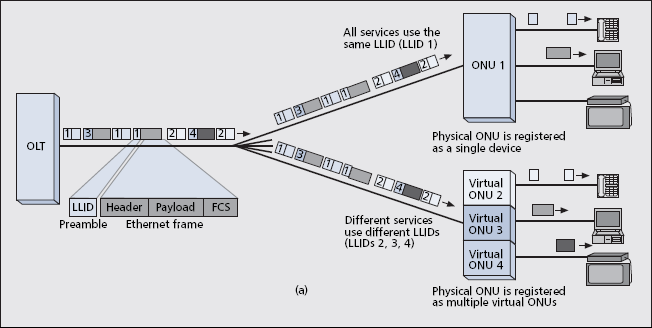
Figure3.4 EPON Downstream Operation
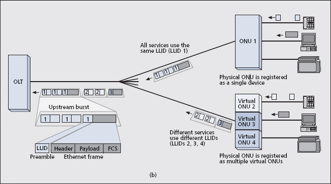
Figure3.5 EPON Upstream Operation
All time-driven events are synchronized to
the PON clock, a 16 ns resolution counter that is
carried in all MPCP messages. The ONU uses
the received timestamp to lock to the OLT time
base. The OLT uses returned timestamps to
measure ONU round-trip delay and schedule
collision-free upstream transmissions.
EPON’s packet preamble contains additional
fields not found in packets sent over P2P
Ethernet links. In downstream transmission the
logical link ID (LLID) field defines the destination
ONU. An ONU filters the received
frames based on the LLID in the frame’s
preamble and its own unique LLID value
assigned by the OLT (Fig. 5a). A special value
is reserved for broadcast messages sent to all
ONUs. In upstream transmissions the LLID
field marks the source ONU (Fig. 5b). A cyclic
redundancy check (CRC) field validates preamble
integrity. Most ONU equipment registers
as a single ONU and uses a single LLID for
data transport. However, some equipment registers
as multiple virtual ONUs, thereby establishing
multiple LLIDs. This allows EPON to
access the same traffic granularity on the PON
as G-PON.
When a physical ONU registers as multiple
virtual ONUs, the OLT treats each virtual
ONU as a separate ONU. Correspondingly, the
OLT grants each virtual ONU separately,
including repeated allocation of the optical
overhead. The OLT also maintains a separate
management channel to each virtual ONU, and
has to identify the SLA allocated to each virtual
ONU.
EPON uses a frame-based FEC mechanism
based on the RS(255,239) algorithm. Each frame
is encoded separately, and all per-frame parity
bytes are added at the end of the frame. This
approach allows ONUs without FEC capabilities
to receive FEC-encoded frames, ignoring the
appended parity data. FEC can be selectively
activated per ONU.
Although not defined in the IEEE 802.3ah
specification, all EPON implementations incorporate
encryption. Encryption is AES-based with
the exception of a special algorithm defined by
the major carrier in China for its network.
EPON MANAGEMENT LAYER:
OAM functionality is another important EPON
breakthrough. Ethernet now includes link layer
management that enables OLTs to remotely
manage attached ONUs.
OAM is established after the discovery process
and is maintained by periodic message
transmission. Information about remote failures
is conveyed using flags in OAM messages to
indicate failure status. The remote ONU can be
instructed to return incoming packets as part of
the remote loopback functionality.
Link monitoring, where any Ethernet variable
of the remote port can be retrieved by the OLT,
is arguably the most useful EPON OAM function.
OAM link information can be extended
beyond the OLT by placing a Simple Network
Management Protocol (SNMP) agent at the
OLT. A soon to be finalized RFC, “Managed
Objects of EPON,” details the EPON MIBs.
An EPON CPE device contains much more
than a MAC. OAM includes vendor extension
mechanisms to provide a convenient and
lightweight method to manage the additional
functionality. This can lead to differing OAM
variants as carriers customize their products.
FUTURE EPON EXTENSIONS
A significant EPON enhancement to run at
higher speed has begun. The IEEE has formed
the P802.3av task force to consider the definition
of an EPON PHY that operates at 10 Gb/s
downstream and 1 or 10 Gb/s upstream. This
enhancement would provide a significant capacity
increase for TDM PON systems.
SIMILARITIES AND DIFFERENCES
Similarities
PON systems in general allow for longer distances between central offices and customer premises, since it can
operate at distances of up to 20 km, which considerably exceeds the maximum coverage afforded by DSL. This
way, the fiber deployment in both local exchange and local loop is minimized, since only one strand of fiber is
needed in the trunk and only one port per PON is required in the central office, which allows for a very dense
CO equipment (smaller footprint) and low power consumption.
PON systems provide higher bandwidth due to deeper fiber penetration. While the fiber-to-the-building
(FTTB), fiber-to-the-home (FTTH), or even fiber-to-the-PC (FTTPC) solutions have the ultimate goal of fiber
reaching all the way to customer premises, fiber-to-the-curb (FTTC) seems to be most economical today, at least
in the cases where the customer population is dispersed and there is an existing in-field copper-based (more
likely DSL) distribution network installed.
Additionally, PON systems allow for inherent downstream video broadcasting (currently, in the form of an
analog video overlay service, in the future - most likely delivered as IP Video), due to their underlying Point-
To-Multipoint structure. Multiple wavelength overlay channels can be added to PON without any modifications
in the terminating ONU modules, thus adding flexibility and extensibility for once deployed fibre plant.
PON eliminates the necessity of installing multiplexers / demultiplexers in the splitting locations, thus
relieving network operators from the task of maintaining and providing power to them. Additionally, PON
allows simplified upgrades to higher bit rates, additional wavelengths and/or advanced modulation formats.
Passive splitters and combiners provide complete path transparency both in terms of data rate and modulation
formats.
Both EPON and GPON systems operate in the upstream channel in the so-called burst mode, where the
transmissions (slots) from the two different ONUs are TDM multiplexed and have a dead zone (guard band)
between them to allow for turning the laser off and on between subsequent transmissions, adjust power levels
(EPON), align to the incoming data stream, and retrieve clock (both EPON and GPON).
In terms of security, all xPON systems suffer from the same set of problems related with the P2M system
architecture due to the underlying physical infrastructure (see Section 4.2 for details). Dynamic Bandwidth
Allocation mechanisms are standardized (along with security mechanisms) by respective responsible
international bodies (IEEE for EPONs and ITU for GPONs).
Differences
EPON systems relay the Ethernet encapsulated data arriving at the LAN subscriber port of the ONU or the
MAN/WAN Ethernet port connected to the OLT. Thus, EPON is a natural extension of the LAN systems and
bridges the gap between the LAN and Ethernet based MAN/WAN structures, which have witnessed increasing
proliferation in recent years. GPON on the other hand uses legacy ATM or novel GEM encapsulation
mechanisms to relay any data streams which are delivered at the subscriber / OLT port. GPON strips the
incoming Ethernet frames (99.500 of subscriber ports are Ethernet based, nowadays) from preambles and
encapsulates them in the GEM frames, in which format they are delivered to the OLT module for further
processing. The incoming data frames are non fragmentable (rules of Ethernet) in EPON systems, while GPON
has the ability to fragment and assemble frame fragments, providing that such a need arises, adding some
computational complexity.
In terms of the data rate, EPON operates at 1.25 Gbit/s data rate (effective data rate 1.0 Gbps) in accordance
with the IEEE 802.3ah standard, but non-compliant systems are available (so-called Turbo EPON) with the
downstream data rate of 2.5 Gbit/s. GPON operates at 1.25 Gbit/s and 2.5 Gbit/s in the downstream direction
(from Central Office to customer) and 155 Mbit/s, 622 Mbit/s, 1.5 Gbit/s and 2.5 Gbit/s in the upstream
direction (from customer to Central Office). GPON is backward compatible with the APON and BPON systems,
and can transport their frames natively. Comparable system set-ups (16 ONUs, 1 logical entity per ONU, similar
data rate - 1.25 Gbit/s for EPON and GPON) produce 9500 efficiency for GPON and 89% efficiency for EPON,
when measured relatively to the pure subscriber payload.
EPON hardware parameters are very relaxed, and thus low grade optical and electronic components can be
applied, minimizing the CAPEX for SPs when deploying the active equipment modules. GPON requires shorter
guard bands and faster electronics (laser drivers, etc.), which significantly increase the technical challenge level
and boost the equipment cost. The hardware layer parameters determine the resulting system price. EPON
systems, due to their lowered hardware requirements, are more cost effective (commonly quoted costs for SPs
include 80 USD per ONU, 450 USD per OLT port). GPON systems, due to their more strict hardware
requirements, are more expensive (ONU costs are 2 - 3 times higher and OLT port cost is roughly 5 - 10 times
higher than for EPON).
GPON deployments are mainly in the trial phase - no real commercial deployments have been reported up to
this moment (04.2007), while EPON had approximately 8 million subscriber ports and 16 million CO port
capacity deployed, by the end of March 2007. The growth rate is of the order of 3 to 4 million subscriber ports
per 6 months, occurring mainly in the Asian market (Japan, Korea, China, etc.). Small deployments are present
in the USA (mainly cable operators) and South America.
NEXT-GENERATION PON SOLUTIONS
Historically, data rates associated with broadband
consumer service offerings have increased
at a rate of approximately 1.3 times/year. This
growth has been driven by services such as convergent
subscription television and the Internet,
high-definition television, digital photography
and video, new models for content production,
distribution, and marketing, possible re-emergence
of thin client computing, and so on. Projecting
this trend into the future, in the long
term we will face bandwidth demands beyond
current G-PON capabilities, requiring R&D in
this field already.
Different groups around the world have
recently started to address this topic. Both
FSAN and IEEE are now discussing ways how
to extend their standards to 10 Gb/s line rates.
Several research projects around next-generation
PON (NG-PON) are investigating the
topic on a wider scope, for example, the European
PIEMAN and MUSE II projects in which
different hybrid network solutions are evaluated
that combine the classical TDM/time-division
multiple access (TDMA) PON with WDM
channel allocations as well as with optical
amplification and transparent long-haul feeder
transport.
Expecting large-scale deployments of GPON systems to start soon, network operators
and system vendors are seeking NG-PON solutions
that can coexist with G-PON on the same
fiber plant and enable gradual network capacity
upgrades. At the same time, it is highly
required to keep the fiber plant as transparent
as possible while moving to NG-PON in order
not to block further evolution paths. The time
consuming and costly deployment of optical
fibers, especially in the distribution plant and
drop sections, must remain in place for
decades without needing modifications or
replacements.
Return to the top